Thursday, May 21, 2015

Multitx User Interface for Review


Hectic user Interface development work is ongoing. Here are the first semi working models. The user interface code (signals) link back to stub functions to the main code. Consider this as a mocup, with some integration already in place.

Please note! This does not remove any of the existing WSJT-X GUI components. This is a new window related to multitx functionality only!

Main Window

Shows the status of:

  • Ongoing QSO
  • Completed QSOs (200 last QSO).
  • Busted QSOs
  • Sponsors in the log.
  • Shows various status messages depending on verbosity level.

Controls:

  • Working Up / Down (or both).
  • Maximum parallel QSO count.
  • Affinity limit for parallel QSOs (affi limit).

image

Area Affinity

I have introduced a new concept that I have dreamed of for many years. Affinity to certain calls / geographical areas. The computer picks the right calls from the pileup for processing based on affinity. Higher the affinity level, the more processing priority the call gets.

Note that the Affi limit comes to play here. If affi limit is set to for example 11 “Work Down” and Japan + VKZL affi limit is set to 12 then ONLY JAs and VKZL stations will be worked DOWN from my CQ frequency. Affi limit 0 (Work Up) enables the rest of the world being worked above. This is not exclusive, i.e. JAs and VKZL will be also worked Up with higher priority, but they get very exclusive treatment with this setup.

image

Call Affinity & Blacklists

What if the operator wants even more fine grained control of what stations to work or what stations NOT to work. The next tab is an effective and simple way to create for example Blacklists. Just set Affi limit to 1 and define Call affinity 0 to certain missbehaving stations. In this case all OH9 stations are blocked and also our local clubstation OH3NE. No qso will be granted to these guys. Sorry!

On the other hand a special treatment will be granted to OH3T, OH3BK and OH1LXF. Note the affinity 50 and affi limit 40 set for “Work Down”.

image

Remember Your Sponsors

Finally, if you are going to a DX pedition and you have sponsors. A nice way to remember them is to give a special treatment at least at some point of the pedition. Sponsors can be give a special high affinity and they can be worked down even if the “work down” is not checked from the first page.

image

Comments are welcome!

Thanks, Toni oh3t

Tuesday, May 19, 2015

JT Multi–Developent Update


A lot of code already in place and lots of tests already been run with the new code.

I try to runt tests immediately when piece of functionality is more or less complete. Very agile development method Iloiset kasvot

I have been running test with five parallel QSOs in different phase and start order.

  • All QSOs are maintained in a two-directional dynamic list.
  • QSO objects maintain their respective QSO state and JT9/JT65 transmit tones.
  • Object constructors and destructors maintain the list integrity and order.
  • Logging functionality is also integrated to QSO objects.
  • Busted QSOs are also handled gracefully and removed from the list.
  • Ongoing QSO may QSY at any phase during QSO Iloiset kasvot
  • New QSO is checked against ongoing ones to safeguard ongoing QSO Tx frequency. No QSO overlap is allowed.

image

Lots of debug printout still left in the code…

image

Biggest single item still missing is the user interface. Maybe tomorrow I can start working on that.

Thanks for reading!

Toni oh3t

Saturday, May 16, 2015

Please Control The ALC!

This is how a bad case of splatter looks like in JT9 waterfall.

image

There is very simple solution for this. I have been educating this to everyone who I have introduced to digital modes.

Step 1: If you have option in your rig to turn ALC (Audio Level Compression) off please do so for ALL digital modes!

Step 2: If you can not turn ALC off you need to set the audio level low enough for ALC not activating and power still going out to the antenna system.

I have found that easiest way to control ALC is with the option: MIC GAIN in my rigs.

This is how perfectly set mic gain looks on the ALC and Power meter:

image

image

About 20 watt going out, Zero ALC activation. You need to explore what is correct mic gain for your audio level.

Here is the same for Yaesu 1000mp.


image

You can see no ALC activation on the ALC meter.

Please clean up your signals!


Toni oh3t

Thursday, May 14, 2015

Multi Tx Development Progress


Finally, after several days of work I was able to run the first on-air tests.

Here are some of the screenshots:

image

In this picture OH3T was calling CQ at 2456 (Hz).

I was remoting OH3NE and replied by clicking the CQ and then immediately moving the Tx freqeuncy to 2161 from the waterfall window. You can see that OH3T keeps on calling CQ on the same time at 2456 throughout the QSO. This is very valuable since, directives can be given and Tx message can be changed from the user interface, while running QSOs on split frequency.

This is how it looks in the waterfall. The IMD is caused by receiving rig saturating due to very close proximity to my home QTH.

image

The implementation is fully scalable with dynamic data structures,  audio mixer, etc. Each QSO can be in different phase. The QSO status is maintained inside a new QSO object structure, and QSO objects are in a dynamic list in frequency order.

Still quite a bit of development to be done before I can go live with this software. For example no user interface yet… Having said that, I think thet the proof is there and this concept is worth developing further.

Hope to CU on the bands!


73s Toni

Friday, May 8, 2015

No I am not a pirate!

Not a pirate!


A friendly HAM sent me an email today kindly noting that someone is pirating my call.

The reason being that on WSJT-X he decoded two transmissions on the same minute from OH3T.

That was not a pirate, that was my development version of WSJTX-multi running one signal on JT65 and another on JT9.

Lets take two steps back..

My Vision

I have university background in signal processing and software sciences. I love digital modes, but I hate RTTY. RTTY is inefficient, breaks easily in congested band, and usually is frustrating mode to work. No pun intended, that mode is just not for me.

I also love working DX. 300+ DXCC in the log.

What if we could make working digital mode DX fun again. I think we can. What I particularly like in JT modes is the structure, powerful encoding in tough band conditions, tolerance to aurora, and the fact that anyone can work DX with JT modes. You do not need massive antennas or linear amplifiers to make a contact with a distant station. This mode is a great equalizer! For example, past 8 days in a row I have logged a VK station on every single day. On the best day 10+ VKs in the log. Most of the stations via long path during the early morning my time.

One of the biggest issues regarding JT9 of becoming de-facto DX digital mode is that it is slow. If we omit sending the grid information we can have one complete QSO in four (4!) minutes. For DX purposes that is way way way too slow QSO rate. Now.. what if we could run multiple QSO at the same time, with one rig?!

I did my first tests roughly 5 months ago. I tediously constructed an audio file of 16 JT9 transmissions. I recorded my CQ calls with virtual audio cable (VAC) and Audacity. I mixed them together in Audacity and then played the audio back to my KX3 and by remoting the local club station OH3NE I was able to see what my transmission looked like. And voila, 16 complete messages decoded. So the concept works.

The maximum simultaneous transmissions so far I have tested the software with (generated by WSJTX-multi) is 40. Again, receiving with the clubstation while the 10 meter band was closed. 10 meter band is a very nice local QSO band here in OH land.

Past few months I have been modifying the JT code and during the past few weeks I have been also testing the software with one transmission only. Now I have added second one, but in another mode. I am trying to avoid confusion, but apparently still generating it. I am sorry for the trouble, but I need to test the software somehow in "production", as software engineers like to say...

Vision Becoming Reality

Still quite a bit of work to be done...

  • Dynamic power output control. 5 watts per signal is reasonable. 20 signals equals 50 watts out. With 200 watt rig or with linear amp the duty cycle is fine. One signal with 50 watt out is bad, so dynamic control is needed.
  • Current user interface is suitable only for one QSO per GUI instance. New user interface is needed for effective multi QSO use.
  • The internal mixer seems to be working fine, but more headroom is needed. Maybe 24bit audio instead of 16bit should be employed.
  • I decided NOT to increase threads in the system. The modulator is looping, generating and mixing the tx signals one by one.
  • Software is prone to errors, the whole QSO concept should be implemented as an object structure to clean up the software semantics.
  • Logging to central DB need to be also included.
  • Better split algorithms needs to be written.

Thanks for reading, CU on the bands!

Toni oh3t

Sunday, May 3, 2015

LoTW Upload 460 QSO since last update

Since last update 460 new JT mode QSOs uploaded to LoTW.

Activity on following bands and antennas:

30m - Moxon at about 16 meter.
20m - 3 el yagi at about 12 meter.
15m - 3 el yagi at about 12 meter.

Thanks again for responding to my CQ calls!

CU on the bands.

Cheers,

Toni oh3t

Monday, April 27, 2015

LoTW Upload


Just uploaded additional 250+ JT mode QSOs to LoTW.

Last QSO in the log:

27.04.15 19:19:00 WB2KEC.

Thank you for all the QSOs over the weekend. Lots of activity!

CU on the bands.


73s, Toni

Wednesday, April 22, 2015

Vertical antenna performance on 40m band

Referring to my previous post I have now tested the vertical antenna on 40m. The antenna tunes nicely to 40 and gives good bandwidth.

image

The pskreporter chart from last night. We had bad aurora around midnight local time but still my station was heard throughout the EU mainland and US east coast. Not bad. Next I will tune the antenna to 80m JT-segment and continue testing.

Friday, April 17, 2015

Simple but effective vertical

At last the snow has melted in Finland. It is time to start planning and constructing some new antennas.
This is an antenna that I have always wanted to construct but never had really time to do it. Simple vertical antenna with coil loading for radiator and optional coil loading for radials. This antenna tunes nicely on 40m and 80m bands. The 80m bandwidth is quite narrow, but in this case it does not really matter, because the main focus is digital with this antenna.

Temporary installation for miniVNA measurements.

Easy to collapse to transportation length. Up and down in less than five minutes.

Measurements with miniVNA with four 10,2meter radials (on ground).

The coil is made from 1.5mm thick wire. Total impedance is 56uH.

image
40m band tunes nicely with decent bandwidth.
image
So does 80m but is very narrow. Good for digital though.
image
Schematic of the antenna. Should be self explanatory Smile
The loading coil for radials can be bypassed by just connecting the radials and the coaxial cable shield directly.

I think antenna is worth trying. I will report the performance after some JT-mode tests.

Tuesday, April 14, 2015

880 JT-mode QSOs uploaded to LoTW

Note to the Logbook of The World users.

I have just made the most recent upload. If your QSO with me is not showing on your LoTW account please do not hesitate to probe me with email.

This upload included 880 JT-mode QSOs with 808 exclusively on JT9 mode (from 53 DXCC entities).

Last QSO in this upload was with M0CLZ at 09:28UTC.

See you on the bands!

Toni oh3t

Monday, April 13, 2015

To CQ or not to CQ?


I have been on 20 + 30m JT9 mode now for few weeks. The band seems to be completely dead, but every now and then I get a QSO.

A dead band is dead if no one is calling CQ or if there is no propagation. And of course if there is no one to communicate with it is tough to make a QSO.

Please activate the bands and call CQ!

Cheers,

Toni oh3t

Digital mode boom in OH land

Over the past few weeks I have been actively promoting JT modes in local HAM radio forums.

I have written emails and local wiki guides with links to various pieces of software.

JT modes seem to facinate many operators. So.. if you see sudden burst of activity from OH land please give these stations nice QSOs!

Cheers,

Toni oh3t

Tuesday, April 7, 2015

Keeping the JT9 bands warm

I think it is the chicken and egg problem.

HAMs continue working JT65 still even it seems to be history. JT9 has significantly less bandwidth (only 16Hz!!) and even better decoding capacity in bad conditions.

I am committed keeping the JT9 signal on air! When I am at (or remoting) my  computer I will call CQ. After a long configuration work I got my Yaesu G-1000DXC rotor also working with my computer and HRD Rotator software. So the rotor is also working with remote commands.

Main bands 15, 20 and 30m. Usually I am calling JT9 CQ around 800Hz (+2 kHz selected) with WSJT-X software.

During the past two weeks I have worked more than 150 stations with JT9 mode, some with more than one band. If you feel like it you can work me several times even on the same band.

Most important thing, let us keep the JT9 bands warm!

Cheers,

Toni OH3T

Saturday, February 8, 2014

Why do I keep getting bad JT9 signal reports?


I have been active on JT9 mode recently. I think this mode has great potential for becoming one of the leading HF digital modes, even for DX-pedition purposes (some tweaks needed though).

I am running digital modes exclusively with my great little Flexradio Flex 1500 and I have a small QRP linear amplifier boosting the signal to 20-30 watts.

Based on reports on-the-air the typical TX power in JT9 mode seems to be between 5 and 30 watts. So I am perhaps running it in the upper end of the scale. Having said that, my normal report is 10-15dB lower than what I send back. This seems to be quite consistent on various bands. So what the heck is happening here?

JT9 has dB in S/N

JT9 is great in tough band conditions and when the conditions are good you can run qrpp and still get great results. The dB in WSJT-X user interface is Signal to Noise ratio (S/N), not the signal strength of the signal you are receiving. Of course, a strong signal usually also means better readability, thus larger S/N dB figure in the user interface.

Instead of me trying to explain the S/N please refer to Wikipedia:

S/N ratio explained

Quad has less noise than Yagi!

I wrote last year in this blog about my Quad project. I have now more experience from this antenna alongside with my yagi. The Quad antenna system has definite edge over the yagi in signal readability! Less static coming from antenna equals better S/N.

I still have the 450 ohm ladder line routed from my ham shack to the tower. The project to move the tuner to the tower is still work in progress and my target is this spring.

quad-twins

Tuner as pre-selector

Due to antenna construction the radiator has to be tuned. My DIY tuner is based on great hiQ S-match design by PA0FRI. This tuner has quite narrow band-pass filter functionality built in.

S-match information

My S-match prototype in the picture (silver coil roller inductor, vacuum capacitor, Amidon toroids, red wire is silicone insulated).

smatch-tuner

The tuner acts as a narrow pre-selector in similar fashion than how magnetic loop antennas work.

This type of antenna matching effectively eliminates noise going to the rig.

Fully digital signal processing chain

Have you ever heard complaints about audio ground loops or RF in audio when you are transmitting? I have suffered perhaps from every issue possible regarding RF and audio problems. Not any more! When I switched to Flex 1500 all those nasty RF and receive noise issues were simply gone. Once the Flexradio has transformed the received signal to I and Q and digitized those the received audio never leaves the computer. The processing from Flex to WSJT-X is done fully digital eliminating all those nasty RF issues. I highly recommend this type of fully digital setup for anyone seriously involved with digital modes.

Location, location, location!

Last but not the least. Perhaps the most overlooked issue is the location of the QTH. As I have written in my QRZ.com profile. “My QTH is one of the highest points in near vicinity and my antennas are 120m above sea level. Nice clear takeoff angle to all the directions with reasonable noise level.”

One of the exceptions regarding the reports was G7APP. I sent –01 and received +01. I checked the location of G7APP from QRZ.com and google maps. No wonder I got such a great report! Great countryside location!

g7app

Final thoughts

I have stopped worrying about the JT9 reports. The report is the indication of one’s working conditions, not necessarily an indication how strong the transmitted signal has been. The software on both ends is the same, the S/N dB calculation is done with exactly same algorithm.

If you constantly receive better reports than what you send, please consider what I wrote above.

Hope to work you with JT9!

Cheers, Toni oh3t

Friday, November 29, 2013

Fun With Flex 1500 and JT-65

CQ CQ

image

In the passband you can see JT65-HF traffic and a little bit below is very active PSK traffic.

image

If you have never tried JT65-HF I definitely recommend trying. It is fun mode to work and very effective during tought band conditions. And even better, you never know who answers when you call CQ. With just 5 watts you can work the whole world!

image

And finally from the pskreporter we can check the propagation. And here we can see that my JT65 transmission is heard in VK and YB land as well.

My quad stack was beaming to NA.

image

Break Is Over

Finally some activity also in this blog.

Antennas are still the same

No improvements to antenna setup during summer :(

I tore a ligament in my right hand during antenna construction just before summer while building new radiator elements for 12 and 10 meter bands. I guess it is needless to say that my summer antenna construction season was basically over before it even started.

Maybe next year with better luck.

Friday, April 26, 2013

Natural High

Natural High for Antennas


What is the best way to launch antennas to trees?

I have been using a fishing rod and a golf ball for quite some time to sling the antenna wires over trees. That setup has been working reasonably well, but it has been lacking accuracy and a bit more height is always preferred.

Here is the my antenna launcher. I found reasonably cheap used long bow. The bow is 44 pounds strong. I drilled a hole to a golf ball and glued the arrow with strong epoxy. Then I shortened an old baitcasting rod and used hose clamps to connect it to the bow.

Monday, March 18, 2013

Foxhunting With a Twist


Over the past several weeks I have been participating to QRP Foxhunting on Sundays and Mondays. The idea is to find low power QRP stations and “shoot them” by making a QSO. This is a friendly event among QRP enthusiasts in EU. The master of ceremonies is Jos, ON6WJ and he coordinates the EUQRPFOX mailing list and the website. Every now and then foxes and hunters are given special themes such as straight keys, vintage rigs, and most recently stealth antennas.
fox67bis2
If you are interested about this activity, please join us by participating the weekly hunts and by subscribe to euqrpfox reflector by following the link below.
Join reflector (mailinglist).
You can find more information from EUQRPFOX website, link below.
EU QRP Foxhunt website
The following is the description of my hunt during the past weekend.

Foxhunting with 92cm magnetic loop

Mission: 60 minutes, foxes on the loose, band 20m, QRP 5 watts, stealth antenna.
image
My home QTH is full of antennas and squeezing yet another antenna seems to be a very difficult task. To avoid antenna coupling I decided to go mobile and run the KX3 from dedicated battery. I charged the battery overnight so it was ready to go on Sunday morning. I did some map searching about possible high places in near vicinity of my home QTH, but could not figure anything that would have the access route on the right side of the hill and have a short drive by car. And I definitely did not want the hill between myself and all the foxes. Instead for opting a high place I decided to drive to a nearby lake. There is a parking lot next to the lake and cross country skiing tracks leaving to all directions so the place should provide good takeoff to EU. The parking lot is on the north side of the lake, so that should favor the southbound and south west antenna directions even further. Google maps. Lake Ruotasjärvi. image View towards south. image I checked everything in my home QTH before finally packing the antenna to the van. When I got to the lake I quickly took the antenna from the van, connected the coax to the loop, and hoisted it up to 4 meters. I tied the rod to the mirror of the Vito for keeping it upright. The capacitor provides reasonably accurate and very fast tuning with the tuning rod. Within few seconds I was able to put loop into SWR 1.0, measured with KX3 and 1 watt. image Then it was time to go back inside the car and put the earphones on and find the foxes. My first reaction was “Oh sh*t!” There was massive contest splatter all over the bands. But hey, foxhunting is not for fainthearted! I started scanning the bands and by luck I found Zoli (HA2PP) hiding a bit above 14,056. Unfortunately he was in and out from the QSB plus terribly in QRM from contest stations. So, I made a mark for this frequency and continued scanning. What made the scanning process especially cumbersome was the very narrow bandwidth of the loop. The practical < 2 SWR was less than 7kHz so I had to retune the antenna every now and then while going up and down the 20m band. Unfortunately, I could not find anyone else so I decided to wait and see if band conditions would improve and I could work the fox station. And then just like a miracle a strong signal came calling CQ EUQRPFOX just a bit below Zoli. My antenna was already tuned for the frequency so I had a little room to maneuver. With help of KX3 I quickly zero-beated to the fox who was calling CQ. I gave my call twice, and yes, Andy (SP9NLI) came back. I think he was as surprised as I was. He was real S5, and coming loud and clear. We quickly exchanged the reports and antenna information. That QSO really made my day! The remaining time I continued waiting for Zoli. There was strong S9++ contest station exactly on the same QRG, I tried to get his attention in between the CQ robot calling test. However, despite my official fox hunting gloves, I could not give a successful shot at this fox. image After the foxhunt, I went to 17m, retuned the antenna and called CQ for few minutes. A couple of stations came back. At this time I was getting a bit cold already despite the beautiful sunshine coming inside the van so I decided to call it a day. Finally I snapped some pictures to my archives. Beautiful weather and very nice field trip on Sunday! image

Best 72s and Happy Hunting!


Wednesday, March 13, 2013

Quad Twins

After a lot of work and struggle, with the kind help from local HAM community I managed to raise the quad #1 to its final height. Once the #1 was up I started the construction of the #2 and I finalized the construction on Tuesday. I snapped a picture of the tower on Tuesday afternoon. The weather was grey and temperature was –7C.
image

Critical Measures

Stacked two identical HRS Quads. Original idea from DK7ZB. Thanks!
5 bands: 10-20.
Feed system, 450 ohm ladder line from shack. Tuner S-match by PA0FRI.
Tower rotating 360 degrees.
Upper quad center height 20m, lower quad center height 9m, stacking distance 11m.

Eznec Model Figures

Eznec calculated performance figures for the stack.
20m
image image
17m
image image
15m
image image
12m
image image
10m
image image
Reasonably good for DX, I think… but always room for some improvement.

Friday, March 8, 2013

Quad vs. Yagi, part 3


On the final day of XT2TT worked them QRP while testing the Quad. Also 9M6 was very loud S9+10 while my quad was pointing to east. Pileup was over 1k wide. I gave my call twice “oh3t/qrp oh3t” and he came back immediately with oh3 oh3 5nn. Very rewarding to test the antenna with good results. I have to admit that I used my old yagi for working Clipperton team TX5K, since I am still a bit hesitant to put kw through my tuner-work-in-progress.

Antenna Bandwidth

Antenna bandwidth is critical aspect of design. I am suffering from snow and icy conditions at least 4 months each year. Resonant antennas can not be designed to be very narrow, since the snow and ice will alter the resonance point and swr significantly.

The yagi design that I have been using as the reference for comparison with the quad can be seen below. I used eznec to calculate the swr and optimized the feed impedance to correspond whet it would look like with the matching stub or for example gamma feed (pick your favorite).

image

As can be seen from the plot the feed impedance for this 3 el yagi is reasonably low. I used 15 ohm as the feed impedance for drawing this plot.

image

image

The reasonable feed swr can be considered to be below 2 for the antenna. The low point for swr < 2 is 14.14 MHz (the upper figure) and the high point for < 2 swr is 14.36MHz. So the < 2 swr range for this antenna is 200kHz. This is fine for example 40m band in EU and plenty for 17m and 24m WARCs but for 20m this is unacceptable.

The point here is not to start optimizing the 3 el yagi but to demonstrate that narrow yagi designs that are optimized for gain and f/b may lead into trouble. Personally I am not a big fan of traditional yagi designs, but prefer the modern OWA designs because of the winter conditions.

Quad and Bandwidth

Traditional quad antennas are equally narrow. One of the main reasons for opting to go with the HRSQ design is the tough winter conditions. The HRSQ is tuner fed, and antenna can be tuned regardless of the snow, ice, and rain. However, the pattern will change as I have already demonstrated in previous analysis.

But lets go extreme. If the resonance point is shifted down and tuner is used to put the antenna into resonance and swr 1.0 the pattern will change.
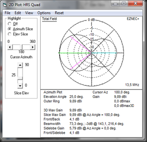
image

Plot with 13.5MHz will revert the pattern, the gain is few dB below the nominal, f/b is destroyed, but I can still keep on working and make contacts with full power.

image

This plot is drawn with 14.5MHz. The pattern has similar characteristics to feeding way below the nominal frequency. The gain is again below the design, but contacts can be made with full power.

Clearly this design due to its nature of feed with tuner and force feeding the antenna has its benefits in tough winter conditions.

HRSQ is clear winner in bandwidth.

Turning Radius

One of the critical design criteria for my tower was to be able to stack the antennas. Stacking has the impact of increased gain and better control over the launch angle. Stacking has also the impact of really pushing down the launch angle below 5 degrees with good gain.

In order to stack antennas one has to avoid the guy wires. High gain 15 and 20m yagis require long booms and in case of my tower setup I do not have the real estate to spread out the guy wires to accommodate long boom yagi stack. Further, I studied the different monoband and multiband yagi options and always run into problem with the guy wires. So I had to optimize the turning radius.

The turning radius for these antennas were calculated for the modeled yagi, HRSQ in diamond and “standard” quad configurations.

Antenna Turning radius, meters
Yagi 4,22
HRSQ Diamond 4,27
HRSQ square “standard” 2,5

So the monoband 20m yagi has a similar turning radius than the HRSQ in diamond configuration, but 1,7m longer than HRSQ in square configuration. So we have a clear winner.

Summary and Final Words

These three articles were covering comparison between quad and 3 el yagi.

Based on the simulation results I would conclude that very few quad myths actually hold true. Quad is not equal to 3 element yagi. Quad is no more fault tolerant to construction errors than yagi. Yagi is clearly better in all performance related metrics compared to quad.

Yagi is the very clear winner in this comparison!

Quad wins in turning radius, and especially HRSQ wins in antenna bandwidth, but that comes with the extra burden of high power tuner in the feed system.

So, how reliable is this comparison? Based on my experience from the models which I have done and the results from field tests and on-air performance comparisons I was referring earlier, the results are very close to what you will get from these antennas.

Of course, quad and loop antenna enthusiasts may say that it is not fair to compare monoband yagi with multiband quad and declare the yagi as clear winner.

Yes I agree, it is not fair. Monoband yagi is superior antenna, but the quad design is very easy to multiband. The point was to demonstrate that quad is very close to yagi, but not superior. The benefits of quad design comes in the next acouple of sentences. In fact all the results and plots in the articles were from monoband yagi and multiband quad. But the results for quad are what they are, even in the multiband setup. So basically, I would say it is reasonably fair to build a quad that is close to 3 el monoband yagi, and get 4 bands for “free” without compromise in performance! It is very fair!

Thanks for reading!